Description
Sophisticated user interface
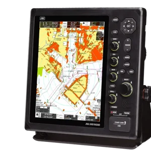
The JMR-9200/7200 series incorporates a new user interface (named jGUI) for an intuitive, easy-to-use, simple menu system based on the display of icons. This interface always displays critical data in fixed positions on the screen while icon-based menu display informs users of corresponding functions straightaway. Furthermore, target tracking (TT) and AIS symbols feature a pop-up displays while mouseover on the target showing their main data at a glance.

Easy-to-use operating unit
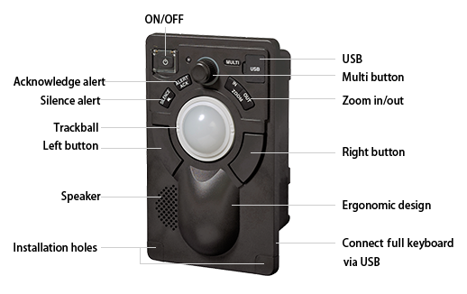
The newly designed trackball supports all the operation of the equipment. Users will be alerted with alarms from the operating unit and color changes under situations that require attention. The radar incorporates dedicated function buttons and control knobs similar to those of conventional models. Furthermore, the radar will be operable like conventional models by connecting an optional operating unit that incorporates a full keyboard.

Solid-state scanner antenna (S-band)
Three solid-state S-band scanner antenna models (including a high-speed rotation model) with two types of radiators (i.e., 8- and 12-ft radiators) have been prepared for the new radar series. Each model incorporates a built-in performance monitor and has MED certification. A solid-state scanner antenna has the following advantages.
- No preheating or tuning required
No preheating or tuning is required. A stable image will be obtained promptly after the power is turned on. - A built-in Doppler filter clearly extracts target objects
Conventional magnetron radars have difficulty in using Doppler filters. A new digital signal processing method has made improvements in target detection performance in clutters. - Magnetron replacement unnecessary
The product adopted a highly reliable Solid state transmission circuit, thus eliminating periodical magnetron replacement and leading to a maintenance cost reduction.
Specifications
| Model | 26-inch type*1 | JMR-9210-6X JMR-9210-6XH | JMR-9225-6X JMR-9225-9X | JMR-9225-6XH | JMR-9225-7X3 JMR-9225-9X3 | JMR-9230-S | JMR-9230-S3 | JMR-9282-S JMR-9282-SH | JMR-9272-S |
|---|---|---|---|---|---|---|---|---|---|
| 19-inch type*1 | JMR-7210-6X JMR-7210-6XH | JMR-7225-6X JMR-7225-9X | JMR-7225-6XH | JMR-7225-7X3 JMR-7225-9X3 | JMR-7230-S | JMR-7230-S3 | JMR-7282-S JMR-7282-SH | JMR-7272-S | |
| Conforming to IMO standards | ✓ | ✓ | ✓ | ✓ | ✓ | ✓ | ✓ | ✓ | |
| Unit configuration | 2-unit configuration | 3-unit configuration*2 | 2-unit configuration | 3-unit configuration*3 | 2-unit configuration | ||||
| Performance monitor | NJU-85 | NJU-84 | Built in | ||||||
| Frequency | X-band | S-band | |||||||
| Display | Color raster scan PPI | ||||||||
| Scanners | |||||||||
| Model*1 | NKE-2103-6 NKE-2103-6HS | NKE-1125-6 NKE-1125-9 | NKE-2254-6HS | NKE-1129-7 NKE-1129-9 | NKE-1130 | NKE-1139 | NKE-2632 NKE-2632-H | NKE-1632 | |
| Antenna length | 6 feet | 6/9 feet | 6 feet | 7/9 feet | 12 feet | 8 feet | 12 feet | ||
| Transmission output | 10 kW | 25 kW | 30 kW | 250 W (solidification) | |||||
| Transmission frequency | 9410 MHz ± 30 MHz | 3050 MHz ± 20 MHz | P0N:3035 MHz Q0N:3065±4 MHz or 3060±4 MHz | ||||||
| Horizontal beam width | 1.2 ° | 6 feet:1.2 ° 9 feet:0.8 ° | 1.2 ° | 7 feet:1.0 ° 9 feet:0.8 ° | 1.9 ° | 2.7 ° | 1.9 ° | ||
| Vertical beam width | 20 ° | 25 ° | 25 ° | ||||||
| Rotational speed | 27 rpm 48 rpm (high-speedrotation) | 24 rpm | 48 rpm (high-speedrotation) | 24 rpm | 24 rpm | 24 rpm 48 rpm(high-speed rotation) | 24 rpm | ||
| Pulse width/Frequency*4 | 0.08 µs/2250 Hz | 0.07 µs/2250 Hz,0.2 µs/2250 Hz | 0.07 µs/(4.6 µs, 8 MHz)/1860 Hz or 2280 Hz | ||||||
| 0.25 µs/1700 Hz | 0.3 µs/1900 Hz,0.4 µs/1400 Hz | 0.14 µs/(9.1 µs, 8 MHz)/1860 Hz or 2280 Hz | |||||||
| 0.5 µs/1200 Hz | 0.8 µs/750 Hz | 0.29 µs/(9.1 µs, 8 MHz)/1860 Hz or 2280 Hz | |||||||
| 0.8 µs/750 Hz | 1.0 µs/650 Hz | 0.57 µs/(9.1 µs, 8 MHz)/1280 Hz | |||||||
| 1.0 µs/650 Hz | 1.2 µs/510 Hz | 1.14 µs/(18.3 µs, 8 MHz)/640 Hz | |||||||
| Duplexer | Circulator + Diode limiter | Circulator +TRHPL | Circulator + Diode limiter | ||||||
| Range scale | 0.125, 0.25, 0.5, 0.75, 1.5, 3, 6, 12, 24, 48, 96 NM | ||||||||
| Motor | Brushless | ||||||||
| Tuning | Auto/Manual | ||||||||
| Ambient conditions | Temperature: -25 to 55 °C (NTG-3225/NTG-3230: -15 to 55 °C); Relative humidity: 93 % @40 °C | ||||||||
| Display unit | |||||||||
| LCD | JAN-9200: 26-inch WUXGA color LCD, 1920 × 1200 dots JAN-7200: 19-inch SXGA color LCD, 1280 × 1024 dots | ||||||||
| PPI effective diameter | JMR-9200: 320 mm min. JMR-7200: 250 mm min. | ||||||||
| Azimuth display mode | North up, course up, and head up | ||||||||
| Operation mode | Relative motion – True trails; Relative motion – Relative rails; True movement – True rails | ||||||||
| EBL | Two (EBL1/EBL2), (Center/Independent), 000.0 to 359.9 °, Four-digit display | ||||||||
| VRM | Two (VRM1/VRM2), 0.000 to 96.0 NM, Four-digit display | ||||||||
| Sea surface/Rain and snow reflection suppression | Auto/Manual | ||||||||
| Trail display | Short (off,15 s to 60 mins.)/Long (off,30 mins to 24 hrs.), Two modes | ||||||||
| Own ship trail records | 24 hours | ||||||||
| User map | 100,000 points | ||||||||
| Off center | 66 % of the radius (excluding 96- NM range) | ||||||||
| Number of TT tracking targets | 100 max. | ||||||||
| TT tracking range | Auto/Manual 32 NM max. | ||||||||
| Number of AIS targets | 500 targets max. (expanding to a maximum 1,000 targets with an optional function added) | ||||||||
| TT/AIS vector | True/Relative, variable from 1 to 120 minutes | ||||||||
| Ambient conditions | Operating temperature: -15 to 55 °C; Relative humidity: 93 % @40 °C | ||||||||
| Power supply voltage | 100-115 V AC, 50/60 Hz,1 φ/220-240 V AC, 50/60 Hz,1 φ/24 V DC | ||||||||
| Option | |||||||||
| Chart radar function | Software license | ||||||||
| Expansion of number of AIS display targets | Software license | ||||||||
| Wave analysis function | Software license | ||||||||
| Keyboard operation unit | NCE-5625 | ||||||||
| Junction box | NQE-1143 | ||||||||
| Interface circuits | CMH-2370(Serial LAN interface circuit)/CMJ-560(Analog option circuit)/CMJ-554(Gyro interface circuit) | ||||||||
| Self-stand frame | CWA-245 (19 inches) /CWA-246 (26 inches) | ||||||||
| Power control unit | NQE-3167 | ||||||||
| Interswitch | NQE-3141-4A (box, up to 4 units) | ||||||||
| Interswitch | NQE-3141-8A (box, up to 8 units) | ||||||||
| Anti-icing antenna*5 | None | NKE-1125-6D/9D | NKE-2254-6HSD | NKE-1129-7D/9D | NKE-1130D | NKE-1139D | NKE-2632D/E | NKE-1632D/E | |
*1 : Each model with the model number suffi x “H” is a high-speed rotation model.
*2 : External transceiver: NTG-3225
*3 : External transceiver: NTG-3230
*4 : The NKE-2632/1632 scanner antennas: Transmission pulse width (1st)/(Transmission pulse width and frequency shift width (2nd))/Repetition frequency
*5 : The supply voltage of each model is shown by the suffi x. D: 100 V AC and E: 220 V AC